Configurable triggers
Acquisition starts with a user-configurable trigger. Each CAN line can be logged independently.
Can-Controller DUAL CAN / STM32
Record two independent CAN lines. Analyze packets. Turn logs into readable data for your project.
Logger, sender and analyzer. WiFi and RTC in the dedicated variant.
01 / TWO NETWORKS, ONE BOARD
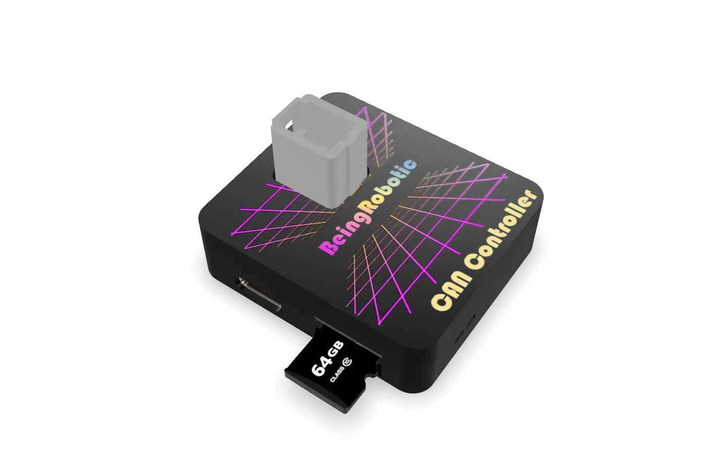
CanController is a multipurpose CAN-bus device for vehicles, embedded systems and motorsport applications where data reliability is essential. It combines power, lightness and versatility.
Two full-speed CAN 2.0B Active interfaces, up to 1 Mbit/s. Modular architecture supports tailored configurations through hardware expansion boards and dedicated software packages.
02 / HARDWARE AND PERIPHERALS
Two CAN interfaces, USB-C connectivity and MicroSD storage: hardware to acquire, retain and analyze bus data.
Functional schematics: they do not show connector positions or wiring. Refer to the datasheet for the pinout.
ORIGINAL MODEL
Rotate the model to inspect the device.
03 / LOGGER & SENDER
Set triggers to log the two buses independently and send packets when a defined condition occurs.
Acquisition starts with a user-configurable trigger. Each CAN line can be logged independently.
All CAN packets are recorded in the proprietary format. The .dbc database determines which messages are converted, while full bus data remains available. Download logs over USB or MicroSD.
Send packets over the CAN line when a user-defined condition is met. Packets to transmit are saved on the MicroSD.
04 / ANALYSIS SOFTWARE
Two complementary tools: configure and convert logs with BeingDecoder, or explore the network in Analyzer mode with SavvyCAN.
Decoder & Configurator manages the board: CAN speed, filters, triggers and other parameters. It converts proprietary logs with a .dbc configuration and lets you choose the conversion frequency.
The resulting .csv files are readable by MegaLogViewer, Matlab and other tools. Each product includes 5 software licenses to convert data from any device.
Explore BeingDecoder →

CanController is fully compatible with open-source analysis software such as SavvyCAN. A USB connection to a PC enables CAN system testing, including packet transmission and reception.
Analyzer mode requires the ST driver and works on Windows 10 and Windows 11.
05 / CANCONTROLLER MANAGER
CanControllerManager switches between Logger and Analyzer and configures the Real-Time Clock (RTC, in the dedicated variant). Available for Windows 10 and Windows 11 with a detailed tutorial.

Steady green LED: Logger mode. Decoder & Configurator creates Config.bei with CAN configuration and triggers. The file can be decoded into .json using a .dbc file available on dbcConverter.
Blinking blue LED: valid configuration and CAN packets detected.
Steady blue LED: Analyzer mode. CAN-bus sniffing and analysis with SavvyCAN.
Blinking green LED: CAN packets detected.

06 / FIRMWARE AND CUSTOMIZATION
The module includes portal access and two free basic applications: one for logging and one for CAN-bus network analysis. Developers can create custom software with STM32-DeveloperTool.
After choosing software, send it over USB, MicroSD or WiFi with the WiFi-equipped variant. WiFi connectivity supports over-the-air updates and behavior changes through the website.
FUTURE DEVELOPMENT
A future software update is planned to program CAN devices over the bus without an additional programmer. Streaming input or CAN data to a remote server for real-time monitoring and remote actuator commands is also planned. These features are listed as future development.

CONFIGURATION EXAMPLE
Local example of the WiFi interface. Values stay on this page and are not sent to a device.
07 / CONFIGURATIONS
Choose the device, add wiring, or include WiFi and RTC with the complete variant.
01 / CAN-CONTROLLER
Base configuration for logging and analyzing two CAN lines.
€189Choose →02 / CAN-CONTROLLER CABLE
The board with a wired connector for your installation.
€199Choose →03 / WIFI + RTC
Includes wired connector, WiFi connectivity and Real-Time Clock.
€209Choose →08 / CUSTOMIZATION
Customize the product with your logo and choose between two colors. Available for orders greater than 10 products.
Request information ↗
09 / DOCUMENTATION
CAN-CONTROLLER
Choose your configuration or tell us about your application.